Sala
- Sala Floor Plan
- Electrical System
- Electrical Installation
- Backup Generator
- PIR lights (motion sensors)
- Dimmer lights
- Light sensors with timer
- Emergency Lights
- Changing Light Bulbs
- Wall Clock
- Ventilation
- Fire Alarm System
- Drainage System
- Sala Main Entrance
- Plumbing
- Audio Equipment Manuals & Documentation
- Skylights
- Disabled Toilet
- Systems operation - Eleonora's notes
- Security Keys Locking Unlocking
- Tea Station
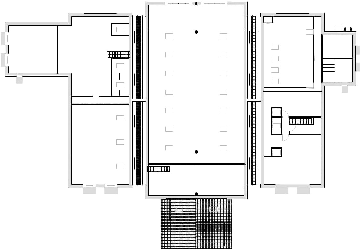
Sala Floor Plan
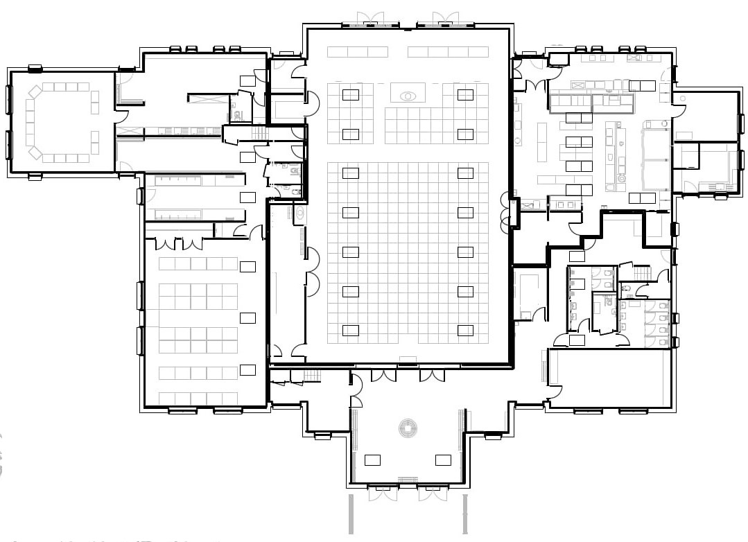
Sala Floor Plan including Outbuildings.jpg

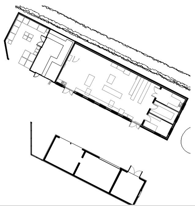
Sala Outbuildings FloorPlan BW.jpg
Electrical System
Electrical system overview and emergency power supply (generator)
Electrical Installation
Nomenclature
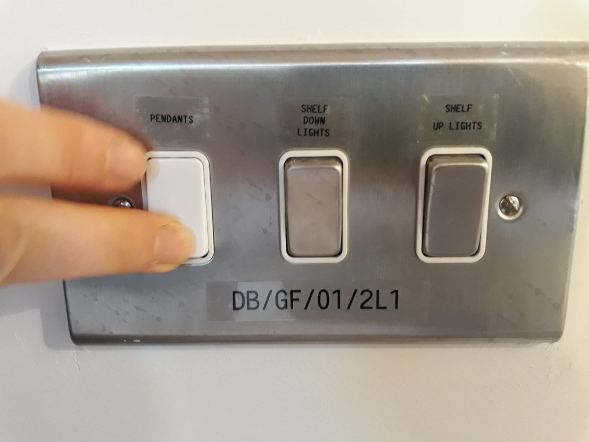
Every switch and sockets are labeled:
BS/xx/xx
eg. DB/GF/01 = Distribution board, Ground Floor, 01 is by the monks eating room
DB/FF/xx = Distribution board, First Floor, xx
"DB/GF/01/2L3"
DB (Distribution Board)/GF (Ground Floor)/01 (Distribution Board Number)/ 2L3 (Circuit Code)
Electrical Distribution Boards
The locations covered by four different Electric Distribution Boards in the Sala:
- Main Hall and Entrance Attic, Monastic Eating Areas (Monks & Nuns) and Sala Attic- DB.GF.01 - located in the Zafu Store on the southwestern side of the Main Hall in the Sala.
- Sala Main Entrance, Multi-Purpose Room, Toilets, Dana Drop-off Area - DB.GF.03 - located in the Cleaning Room near the entrance to the toilets.
- Kitchen, Flower Studio, Kitchen Attic - DB.FF.KT - located in the northern room in the Kitchen Attic.
- Emergency Power Supply from Generator- DB.FF.ESS (Essential Services) - located in the northern room in the Kitchen Attic.
Please note that the below layout plans below are 'Design Diagram' these will vary to has actually been installed. ADL are waiting for 'As Building Drawings' from the electrical contractor which will show what was actually installed.
Location of Ground Floor Stairs Distribution Board: 6743-MXF-XX-00-DR-E-23100.pdf Please note that DB.GF.02 was not installed.
Location of Upper Floor Distribution Boards 6743-MXF-XX-01-DR-E-23100.pdf
Wiring
All the wires to the light switches descend vertically from the ceiling. There should never be any drilling done in this part of the wall.
Backup Generator
The petrol generator is in the Main Electrical Room on the side of the workshop.
What is powered in the Kitchen
- Sockets in the back wall (washing up)
- Heat Pump ?
- Hot Water ?
Procedure
- Move it with its cable outside the Kitchen
- Plug the cables and the earth to the generator
- Check fuel and oil
- Start
- Turn on switches on sockets
- Turn on Main switch in attic
Log
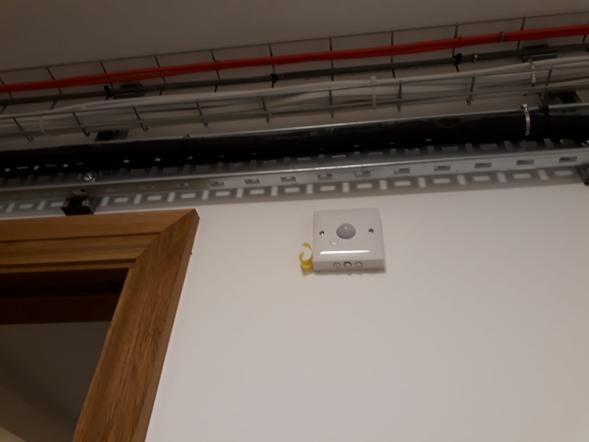
PIR lights (motion sensors)
No manual light switch in according areas
-disabled toilets (timer inside toilets besides ceiling light)
-all toilets (timer in the toilet besides ceiling light)
-monk's store room by the coat & shoes hall way
-nun's pigeon area (timer besides ceiling light)
-sluice / cleaning room (timer inside besides the door)
-lobby area (timer in the sala storage near monk's eating area entrance)
Disabled Toilets
To change the timer or the intensity one needs to pull the light down about 2cm. This allows access for a screwdriver to turn the switch.
Dimmer lights
Only in monks' and nuns' eating areas.
The dimmer light (white button) has a memory, so if you turn it on with a short hold it will automatically set itself to the previous brightness.
Press and hold to set the strength of the lights.
To dimming up or down, switch off and switch on and hold.
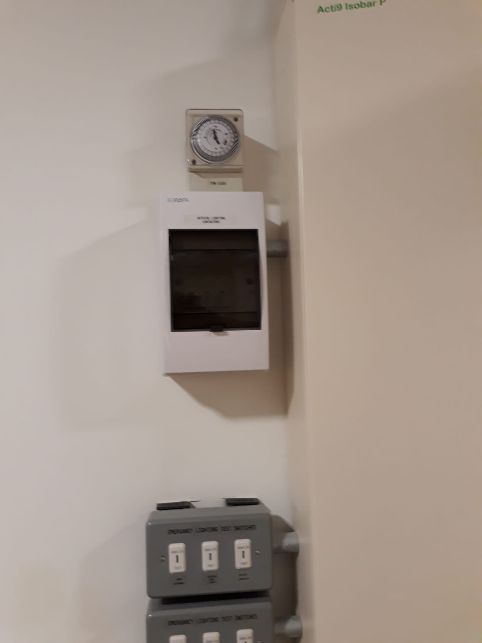
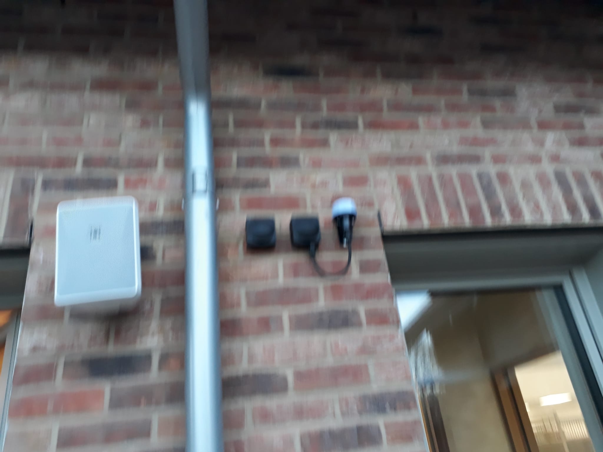
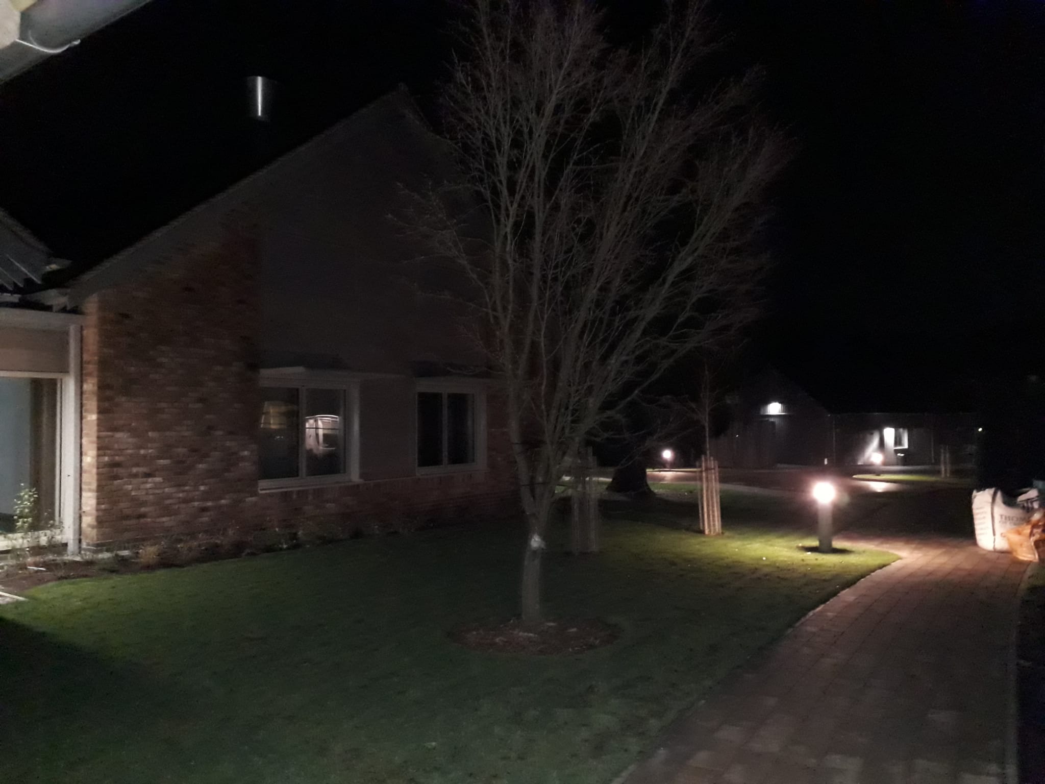
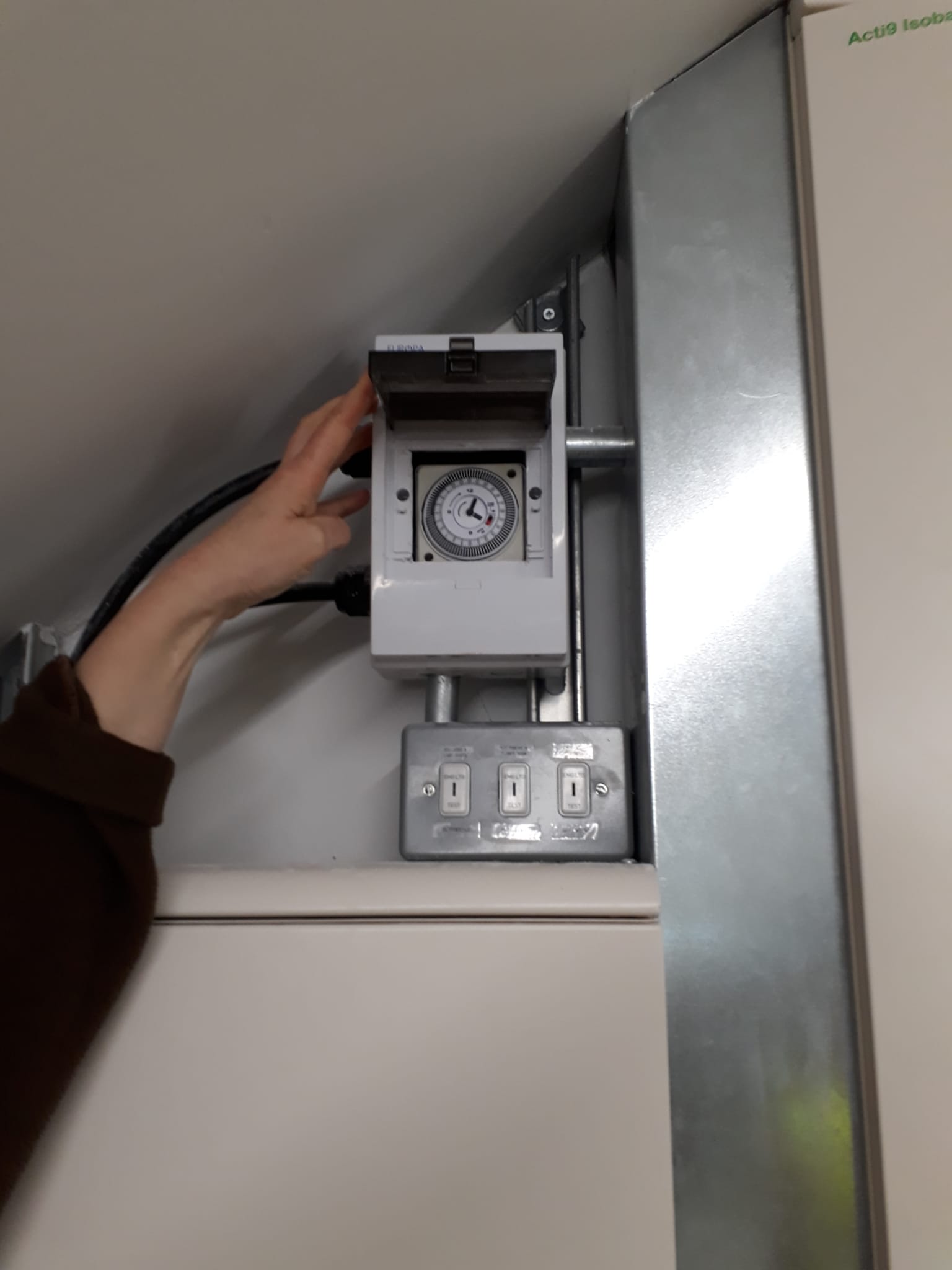
Light sensors with timer
Pendant light outside the main sala porch and lights in the sala lobby (shoe area) (2 X LED, 2 X pendant lights)
These lights are controlled by two sensors:
1) An analogue timer (this takes priority; so the lights can be automatically programmed to turn off during the middle period of the night).
2) Light sensors.
Lights gets automatically turned on/off via a light sensor that is activated by a timer (now set at 4 am - 10 pm). Since it is analogue, it will need resetting if we have a power cut.
For instance, light sensor automatically turns on / turns off the pendant light outside the main sala porch and lights (2 X LED, 2 X pendant lights) in the lobby when it detects darkness / light outside surrounding area.
Locations
of the light sensor: Adjacent to the external sounder - for porch and sala lobby only.

of the timer: sala storage room (beside the fuse box)
All external lights between eastern side entrance of sala and workshop
Locations
of the light sensor: next to dana entrance on the right
of the timer: kitchen attic store
There is also a timer in the workshop.
Emergency Lights
- Next to Breaker Switch
- Need key to rock switch
These need to be tested once a year by.a professional.
If the green light is blinking it is probably due to a fault.
These have 2 power supplies. When the professional does the test they kill the permanent power supply to see if the battery is still working. The battery should last a minimum of 3 hours.
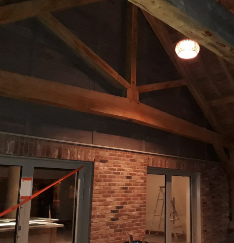
Changing Light Bulbs
Most of them in the building are integral and cannot be changed by us.
In the main chamber, the ones embedded in the shelf pointing downwards, and the ones on top of the shelf can be changed by us.
Every light bulb has a driver, so if you change a bulb and it doesn't work it is because the driver is faulty.
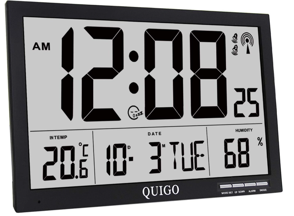
Wall Clock
- QUIGO Large Digital Wall Clock Radio Controlled 100 GBP

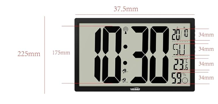
36.6W x 36.5H centimetres - Youshiko XXL 14.76'' Jumbo LCD Radio Controlled 59.99

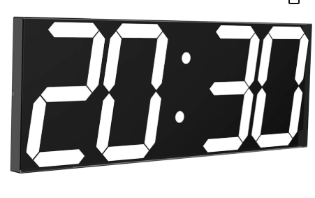
37.5W x 22.5H centimetres - CHKOSDA Digital Wall Clock 75

45W x 16H centimetres
Ventilation
Ventilation system and air treatment units (MVHR) – Controls and maintenance
CO2 Meter
SenseAir is a high-quality CO2 meter that measures CO2 as well as temperature and relative humidity to monitor the indoor climate. It comes with a power adapter and does not work on batteries.

Why do we measure CO2?
CO2 is often measured in indoor environments to quickly serve as an indication if additional ventilation is required. Because CO2 is a known indoor pollutant, too much CO2 can also affect human performance, productivity, and overall health.
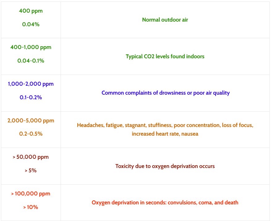
What is an acceptable CO2 level in a room?
Normal CO2 levels in fresh air is approximately 400 ppm (part per million) or 0.04% CO2 in air by volume. The table below shows the effects of increased CO2 levels in an enclosed space.
Temperature and Humidity
- Temperature: Higher temperatures can increase the rate of CO₂ emissions from certain sources and influence ventilation effectiveness.
- Humidity: High humidity levels can affect the performance of ventilation systems and indoor air quality.
Ventilation
- Air Exchange Rates: Higher ventilation rates generally reduce CO₂ levels by increasing the exchange of indoor air with fresh outdoor air.
- Ventilation System Efficiency: The effectiveness of MHVR systems in circulating and filtering air impacts CO₂ levels. Poorly maintained systems can lead to elevated CO₂ concentrations.
Building Structure and Insulation
- Building Tightness: Well-sealed buildings may trap CO₂ indoors, leading to higher concentrations if ventilation is inadequate.
Occupancy
- Number of People: The more people present in a space, the higher the CO₂ levels, as humans exhale CO₂ with every breath.
- Activity Level: Higher activity levels (e.g., exercise or movement) increase CO₂ production per person.
Ventillation Schedule
Sala
Cold draft in the sala when the ventillation is on. If the vents can be tilted upward, the cold draft might not be a problem and so the timetable might not need to be taking that in account if tilting the vent works
|
Start (Winter) |
End (Winter) |
Start (Summer) |
End (Summer) |
Activity | Need |
|---|---|---|---|---|---|
| 7:15 | 8:30 | 7:15 | 8:30 | Breakfast & Meeting | No draft |
| 10:30 | 12:30 | 11:15 | 13:00 | Anumodana & Eating | No draft |
| 12:30 | 13:30 | 13:00 | 14:00 | After eating | Airing the room to remove food smell |
| 17:00 | 19:00 | 17:00 | 19:00 | Tea & reading | No draft |
Monk's & Nun's Area
We don't feel draft in the monk's area so it is not a problem if the ventilation is on during activity.
|
Start (Winter) |
End (Winter) |
Start (Summer) |
End (Summer) |
Activity | Need |
|---|---|---|---|---|---|
| 10:30 | 12:00 | 11:15 | 13:00 | Meal | No draft |
| 12:00 | 13:00 | 13:00 | 14:00 | After eating | Airing the room to remove food smell |
Kitchen
|
Start (Winter) |
End (Winter) |
Start (Summer) |
End (Summer) |
Activity | Need |
|---|---|---|---|---|---|
| 9:30 | 10:45 ? | 9:30 | 11:15 | Cooking | Removing smoke and steam |
MVHR videos from Swegon
work in progress
Link to the Swegon videos in google drive
Fire Alarm System
Operation and testing of the Fire Alarm System in the Sala. Will include fire alarm zones and detectors location map
Fire Alarm
Fire Alarm and Emergency Light Testing
Fire Alarm Call Points
- Instructions for Fire Alarm Testing in the Sala Instructions for Fire Alarm Testing in the Sala.pdf
- Sala Fire Alarm Test Sheet Sala Fire Alarm Test Sheet.pdf
- Workshop & Garden Stores Alarm Test Sheet Workshop & Garden Stores Fire Alarm Test Sheet.pdf
- Call Point Location Plan 1 (Ground Floor) vs3.pdf
- Call Point Location Plan 2 (Upstairs) vs3.pdf
- Call Point Location Plan 3 (Workshop & Garden Stores) vs4.pdf
![]()
Emergency Lighting
- Sala Emergency Lighting Test Sheet
- DRAFT Sala Emergency Lighting Plan
- Emergency Light Switches Location Plan 1 (Ground Floor) vs3.pdf
- Emergency Light Switches Location Plan 2 (Upper Floor) vs2.pdf
- DRAFT Workshop & Garden Stores Emergency Lighting Plan
- Emergency Light Switches Location Plan 3 (Workshop & Garden Stores) vs3.pdf
Fire Alarm Panel User Instructions
- Sala Fire Alarm Panel User Instructions Advanced-MxPro5-User-Manual.pdf
- Workshop Fire Alarm Panel Information GO1.pdf
- Call Point Installation & User Guide Intelligent Manual Call Point Installation Guide.pdf
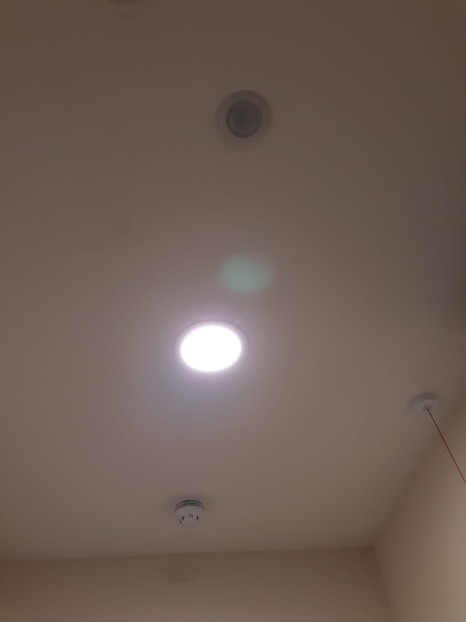
Smoke/Heat Detectors
Sala & Workshop - Smoke Detector Alarms with numbers vs2.pdf
There is a 3 minute delay on the fire alarm sensors (smoke alarms, heat sensors). This means that if one discovers a fire and the sirens are not alarming you should press a call point immediately (every second counts!). The call points do not have a delay.
If there is a fault with the fire alarm panel it will make a high pitched tone (only in the vicinity of the panel). The fire alarm company need to be alerted as soon as possible, and once this is done the tone can be silenced using the 'mute' button.
The fire suppression system in the kitchen uses foam. It will be triggered automatically if there is a substantial kitchen fire. If this is triggered it requires A LOT of cleaning up afterwards!!!!!!!!
If a smoke alarm has been triggered (either by smoke or something else) it will have a red light showing on the sensor. This is a way that a faulty detector can be identified.
To gain more information about the location of a fire alarm test/trigger, press the menu button on the panel ('tick' icon) and then scroll to the right (??).
If there is a fire on the wok or the oven turn off the fuel supply by pressing the red button in the corner of the kitchen. To reconnect the fuel, pull the button out.
Other Files
2024-11-09 Phase 6s Sala Fire Safety System Commission Certificate.pdf
Ground Floor Fire Alarm System (Design Plan): 6743-MXF-XX-00-DR-E-40100 (1).pdf
Upper Floor Fire Alarm System (Design Plan): 6743-MXF-XX-01-DR-E-40100 (1).pdf
Fire Alarm Zone Map: Sala Fire Alarm Zone Map.pdf Sala Fire Alarm Zone Map.pdf
- Outside Lighting & Escape Route to Assembly Point: Sala Outside Lighting & Escape Route to Assembly Point.pdf
Videos From the Training
Drainage System
Drainage System – Maps & Drawings
Map of the 6s drainage system
(Sala, Kitchen and Service Yard)
Drainage construction details
Attenuation Tank details
Soakaway details
Maintenance schedule of attenuation Tank
Contacts for cleaning and maintenance
Drainage System – Info & Maintenance
Drainage system info
(includes map and sample of cleaning schedule)
Contacts for drainage maintenance:
work in progress
Drainage cleaning calendar
(see Maintenance Calendar (link)
work in progress
Sala Main Entrance
Items to do with the main entrance to the Sala
Coping Stone - Repair Methodology

Equipment and Consumables
Equipment
1. Flat plywood board (30 cm square max) to mix the mortar.

2. Small craft trowel to mix the mortar and fill the damaged stonework.

Consumables
1. White Masonry Filler

2. Sand (Regular orange coloured builder sand)

3. SBR (rubber based water resistant bonding agent)

Instructions
Make sure the area being repaired is clean, free from dust, dirt of plant life. Mix a quantity of sand and white masonry filler together to form a homogenous mixture. Gradually add a little SBR and mix the mortar until this becomes a stiff paste. The mortar can the be applied to the repair using the small trowel.
Green Oak Frame - Tannin Removal
- Oak contains ochre coloured tannins which are water soluble and wash off in the rain.
- These have stained the masonry underneath the oak frame.
- It's best to wait for around a year for all the tannins to leach out of the green oak before attempting to clean the masonry.
- The ochre tannins may also wash off the masonry over the course of this period. After which the remaining tannins can washed off.
To clean tannin stains from masonry, you can try washing with water and scrubbing with a brush, or using a tannin stain remover. For severe stains, you may need to repeat the process.
Steps
- Clean with detergent: Use a quality detergent to remove any added substances. Avoid soap, which can make the stains harder to remove.
- Apply tannin stain remover: Use an acid-based tannin stain remover to dissolve the tannin.
- Scrub: Scrub the stain with a brush or broom.
- Rinse: Rinse the area thoroughly with clean water.
- Repeat: Repeat the process if necessary.
Plumbing
Valves
Hot Water in the Kitchen
All the sinks have mixer valves below the basin which mean the temperature should never be scolding.
The boiler is heated by the Air Source Heat pump which is outside the kitchen.
From the boiler the hot water goes to either the underfloor heating, or these 3 zones for hot water:
1) Kitchen
2) Monks and nuns areas
3) Lay toilets
Water Distribution Layout: 6743-MXF-XX-00-DR-P-20100.pdf
Water Softener (TAC system)
This is located in the second storage room in the kitchen. All potable water entering the monastery is treated by the TAC system and helps to reduce limescale. The large TAC tank needs to be replaced after two years (next change: November, 2026).

Two types of Hot Water being generated
- Air source heat pump (ASHP)
- Heat pump water heater (HPWH)
What's the difference between the two?
Air source heat pump provide space heating (via radiator or underfloor heating) and hot water whereas heat pump water heater design for hot water use only.
Air source heat pump (ASHP)
Air source heat pump transfers heat from the outside air to the water in the central heating system. It provides space heating (UFH - underfloor heating ) in sala and monastic eating areas and hot water to the kitchen.
Where? Cylinder in the kitchen washing up zone


 Top right cylinder hot water tank for underfloor heating
 Bottom left cylinder hot water tank for kitchen
Immersion heater - backup supply hot water. It powers by electricity and it takes 1.5 to 3 hours to heat up the tank.
When ASHP failed, immersion heater comes on automatically. Once the desired temperature ~ 60°C has been reached, it cut off the supply.
Heat pump water heater (HPWH)
HPWH gather ambient warmth from the air and compress it to heat up the water. It provides hot water to the monks' and nuns' bowl washing sinks
Where ? Cylinder in the Sala Attic


Hot water - electric heaters
There are 3 of these:
1) Sluice room

2) Flower room

3) Public toilets

Underfloor Heating
There are two sensors measuring the temperature:
1) Ambient temperature (black screen on the wall at head height)
2) Screed temperature control panel (at ankle level - white coloured) - this should not be adjusted.
We should never drill into the floor because it is highly likely to damage the pipes.
Five Underfloor Heating Zones: 6743-MXF-XX-00-DR-M-15100 (1).pdf
Category 5
Category 5 water is a fluid that poses a serious health risk due to the presence of: Pathogenic organisms, radioactive or toxic substances, human waste or fecal matter.
Water supplied to:
- Ablution Hoses in Toilets.
- Outdoor External Taps.
- Outdoor Mop Cleaning Station (Kitchen).
- Workshop and Recycling Area.
- Spray Down Area next to Gardening & Grounds Equipment Stores.
Have been deemed to fall under the Water Supply Regulations and required to be served by water pipes separated from the main potable supply to prevent contamination. They pass through a pressurized Break Tank located in the Kitchen Attic which prevents backflow of any chemicals and swimming microorganisms contaminating the potable water supply. See Green Lines in the Water Distribution Layout.
Nomenclature
MCWS = Mains Cold Water Service
BCWS = Boosted Cold Water Service (Category 5 water via break tank to supply ablution hoses, outside taps, the Workshop etc.)
Monks' Bowl washing room
The valves for the sinks can be accessed by removing the metal sheets at the back of the cupboards underneath.
Nuns' Bowl washing room
Water shut off valves of two types.
- Lever handle valve - first sink close to the towels hanger

- Slotted screw valve - rest of the sinks


Audio Equipment Manuals & Documentation
Microphones
AKG D5 S Dynamic Microphone
AKG D5 S Microphone Quickstart Guide: AKG_D5S_D5LX_Quickstart_Guide.pdf
AKG D5 S Microphone Manual: AKG_D5_D5S_Manual.pdf
AKG D5 S Microphone Service Documentation: AKG_D5_D5S_Service_Documentation.pdf
AKG D5 S Microphone Information Sheet: AKG_CutSheet_D5_S.pdf
AKG D5 S Microphone Polar Pattern: AKG_D5_D5S_D5LX_Polar_Patterns.pdf
Shure SM58 Dynamic Microphone
Shure SM58 Microphone User Guide: SM58 User Guide - Shure.pdf
Microphone Accessories
Shure GLXD24+ Wireless Microphone Receiver
Shure GLXD24+ Receiver User Guide: GLXD4+ User Guide - Shure.pdf
Shure SB904 Lithium-Ion Rechargeable Battery
Shure SB904 Battery Compatibility Chart: Shure Rechargeable Battery Compatibility Chart (English).pdf
Shure SB904 Battery Guide to Rechargeable Lithium-Ion Batteries: guide-to-rechargeable-lithium-ion-batteries.pdf
Shure SB904 Battery Declaration of Conformity: SB904__UK_DoC.pdf
Mixing Consoles
Yamaha MG10 10-Channel Mixing Console
Yamaha MG10 Mixing Console Owner's Manual: mg10xufOwnersManual.pdf
Yamaha MG10 Mixing Console Owner's Manual Sheet: mg10xOwnersManual.pdf
Yamaha MG10 Mixing Console Technical Specifications: mg10xTechSpecs.pdf
Yamaha MG12XU 12-Channel Mixing Console
Yamaha MG12XU Mixing Console Owner's Manual: mg12xukOwnersManual.pdf
Yamaha MG12XU Mixing Console Technical Specifications: mg12xTechSpecs.pdf
Power Amplifiers
Crown DCi4 300 Power Amplifier
Crown DCi4 300 Amplifier Operation Manual: 5040449-B_DCi Series_Analog_Input_Manual_062422.pdf
Crown DCi4 300 Amplifier Data Sheet: DCi DataSheet 010915.pdf
Crown DCi4 300 Amplifier Declaration of Conformity: Amplifiers DriveCore Install Family DoC - 3rd Nov 2021.pdf
Crown DCi4 300 Amplifier Web Brochure: DCi_Brochure_CRO447_052915_Web.pdf
Crown DCi4 300 Amplifier Power Draw Thermals (excel): DCi_Analog_Power_Draw___Thermal.xlsx
Crown XLi 800 Power Amplifier
Crown XLi 800 Power Amplifier Operation Manual: 5024247_SPEC_MNL_XLI_OPERATION_0413.pdf
Crown XLi 800 Power Amplifier Data Sheet: XLi_Data_Sheet_lowres_121914.pdf
Crown XLi 800 Power Amplifier Power Draw: CRN_XLI_TSG_ACPowerDraw.pdf
Crown XLi 800 Power Amplifier Declaration of Conformity: Amplifiers(XLi_800__XLi1500__XLi2500__XLi3500)_DoC_7-7-14.pdf
Zone Distribution Processors
dbx ZonePRO 1560 Digital Zone Processor
dbx ZonePRO 1560 Digital Zone Processor Manual/Install Guide: ZonePRO Install Guide 5059565-B.pdf
dbx ZonePRO 1560 Digital Zone Processor Connectivity & Association: ZC_controller_connectivity_and_association.pdf
dbx ZonePRO 1560 Digital Zone Processor Quick Start: ZonePRO_Quick_Start_5059564-A.pdf
dbx ZonePRO 1560 Digital Zone Processor Application Guide: ZonePRO App Guide.pdf
dbx ZonePRO 1560 Digital Zone Processor Data Sheet: dbxZonePRO1260DataSheet.pdf
dbx ZonePRO 1560 Digital Zone Processor Safety: ZonePRO Safety 5059561-B.pdf
dbx ZonePRO 1560 Digital Zone Processor Brochure: dbxZP_Brochure.pdf
Omnitronic MZD-88 Matrix Zone Distributor
Omnitronic MZD-88 Matrix Zone Distributor Owner's Manual [German & English]: Omnitronic MZD-88.pdf
Loudspeakers
JBL 8124 4-inch Ceiling Loudspeaker
JBL 8124 Loudspeaker Specifications: 8100-SERIES.pdf
JBL 8124 Loudspeaker Tunings: Commercial_CBT_Speaker_Tunings_220616.pdf
JBL 8124 Loudspeaker Accessory Compatibility Guide: JBL Pro Ceiling Speaker Accessory Guide Jan 2024.pdf
JBL 8124 Loudspeaker Declaration of Conformity: JBL_8124_8128_v1.pdf
JBL Control 25-1 5-inch Outdoor Loudspeaker
JBL Control 25-1 Loudspeaker Specifications Sheet: Control 25-1 Spec Sheet Review.pdf
JBL Control 25-1 Loudspeaker Tunings: Commercial_CBT_Speaker_Tunings_220616.pdf
JBL Control 25-1 Loudspeaker Attachment of Speakers: DOC_1371.pdf
JBL Control 25-1 Loudspeaker Invisiball Installation: invisiball.pdf
JBL Control 25-1 Loudspeaker Painting Loudspeaker Cabinets: Painting HIPS Loudspeaker Cabinets.pdf
JBL Control 25-1 Loudspeaker Weather Resistance Panel Covers: MTCPC2PC3 Instructions 160322.pdf
JBL Control 25-1 Loudspeaker U Brackets: CC_Surface_Bracket__20Instr_160328_X3.pdf
JBL Control 25-1 Loudspeaker Declaration of Conformity: CONTROL-CONTRACTOR-SERIES.pdf
JBL Control 26CT 6.5-inch Ceiling Loudspeaker
JBL Control 26CT Loudspeaker Owner's Manual: DOC_1048.pdf
JBL Control 26CT Loudspeaker Tunings: Commercial_CBT_Speaker_Tunings_220616.pdf
JBL Control 26CT Loudspeaker Specifications Sheet: Control 26C and 26CT Spec Sheet Review.pdf
JBL Control 26CT Loudspeaker Technical Application Guide: csapp.pdf
JBL Control 26CT Loudspeaker Accessory Compatibility Guide: JBL Pro Ceiling Speaker Accessory Guide Jan 2024.pdf
JBL Control 26CT Loudspeaker High Humidity Grilles: JBL_MTC-14WG16WG_20v4.pdf
JBL Control 26CT Loudspeaker Grille Safety Tether: JBL_MTC-CS-Teth1_Safety_Tether_Instructions_V2BW_6_30_21 Final.pdf
JBL Control 26CT Loudspeaker Declaration of Conformity: CONTROL-CONTRACTOR-SERIES.pdf
JBL Control 227C 6.5-inch Coaxial Ceiling Loudspeaker
JBL Control 227C Loudspeaker Owner's Manual: DOC_1019.pdf
JBL Control 227C Loudspeaker Specifications Sheet: Ctrl227C_CT_v2_specsheet.pdf
JBL Control 227C Loudspeaker Architectural Specifications: 227C_ArchitecturalSpecs.pdf
JBL Control 227C Loudspeaker Tunings: Commercial_CBT_Speaker_Tunings_220616.pdf
JBL Control 227C Loudspeaker Backcan Assembly Instructions: 227 Install Sheet.pdf
JBL Control 227C Loudspeaker Accessory Compatibility Guide: JBL Pro Ceiling Speaker Accessory Guide Jan 2024.pdf
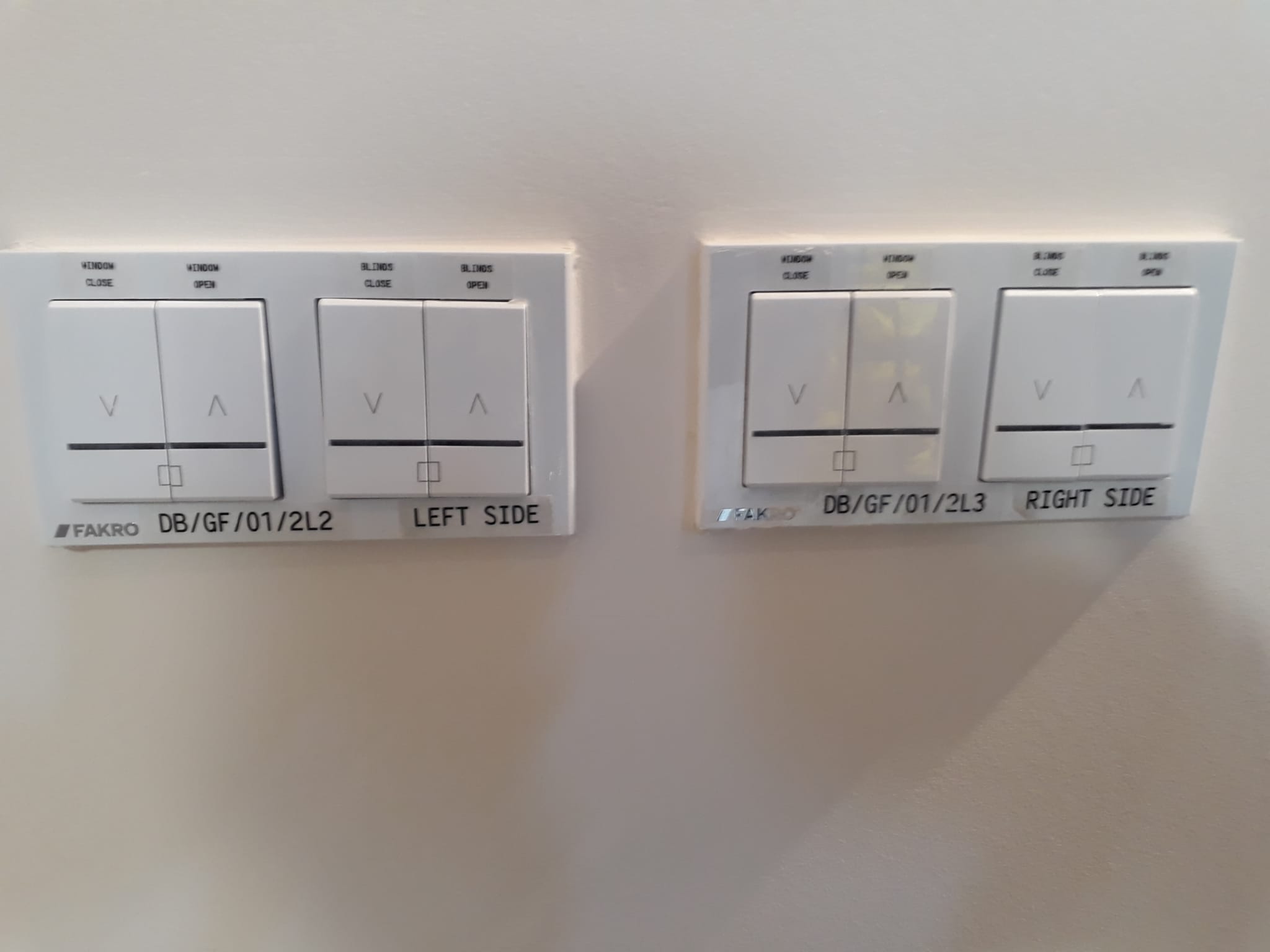
Skylights
The Sala skylights are the only ones with Blinds
The switch panels for the blinds and windows are in the servery area near to kitchen lobby.
There are separate panels for either side of the main chamber (enlarge the photo to see this).
The blinds can only be opened or closed when the windows are closed.
The skylights will automatically close when there is rain/snow.
However, the windows should always be closed at the end of the day.
The other skylights do not have blinds
All skylights have switches for opening and closing.
The skylights will automatically close when there is rain/snow.
If there is a problem with the skylights in the main chamber it might be a problem with a RF communicator (relay device). These are sitting on top of the shelf along the sides of the room. This will need either the maintenance person or a professional to deal with it.
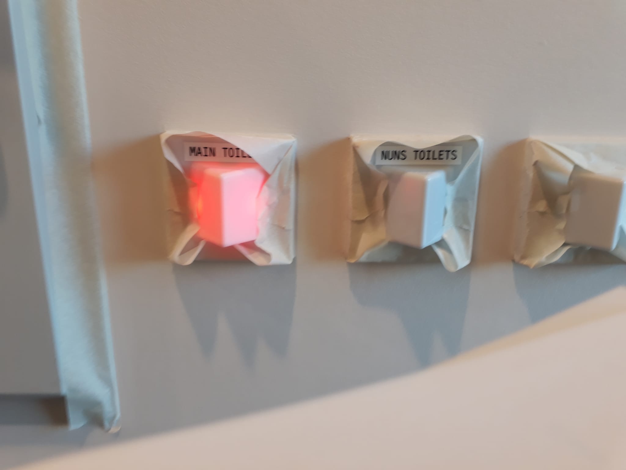
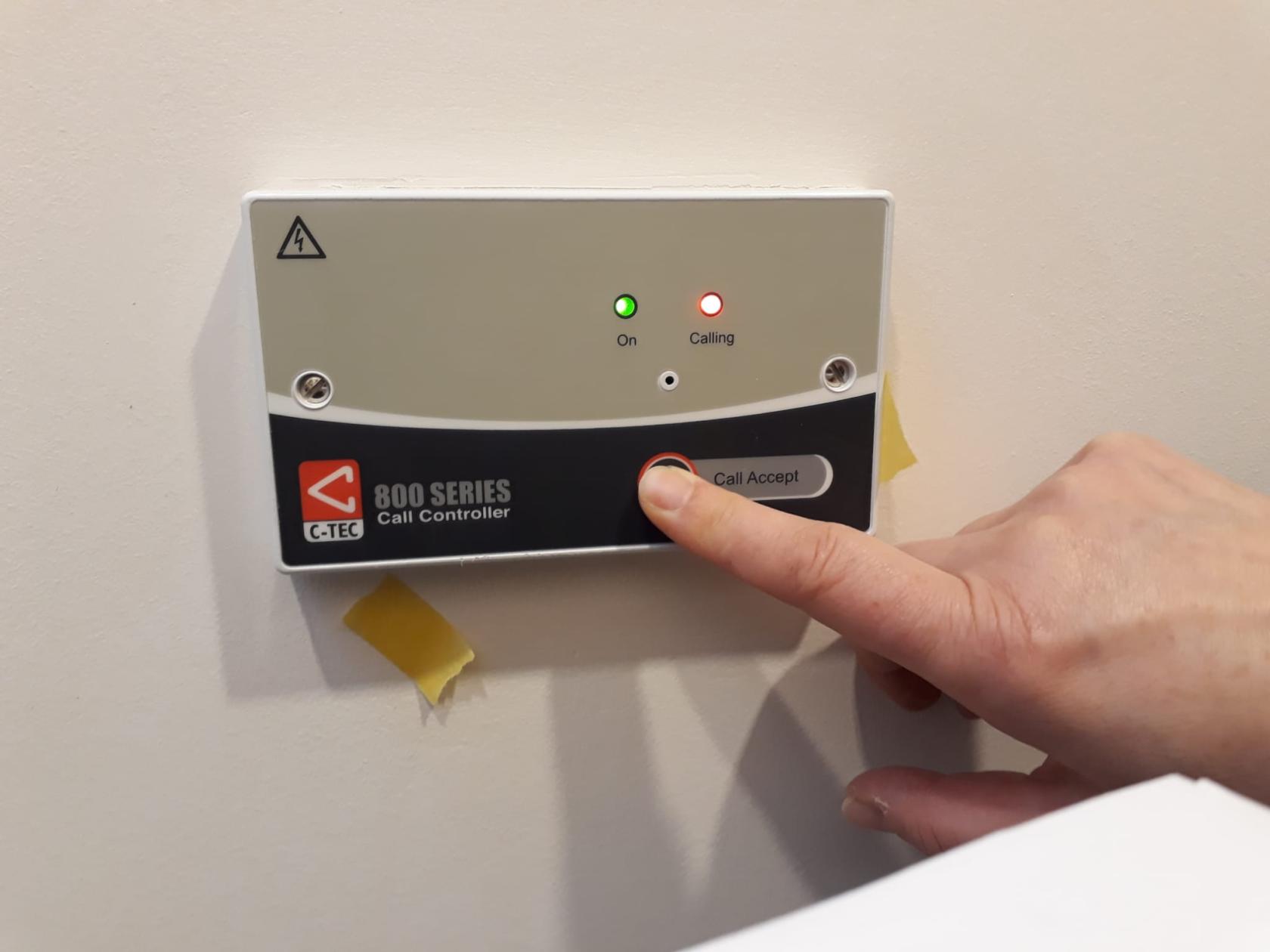
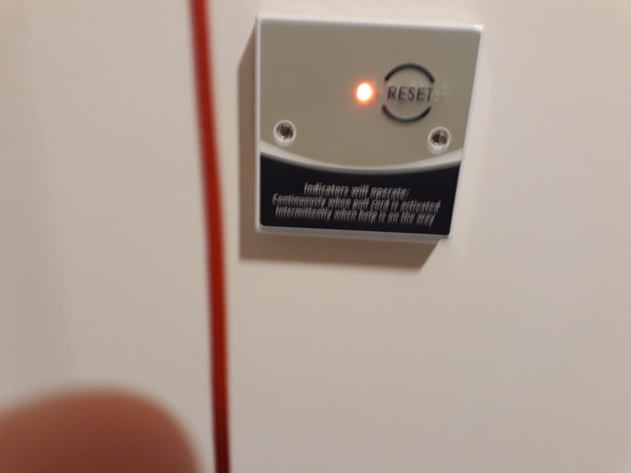
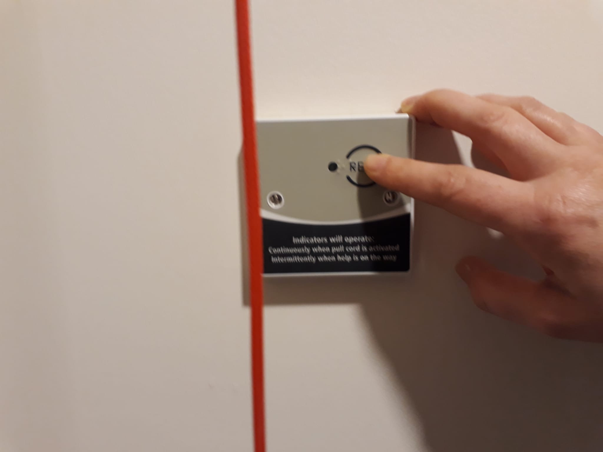
Disabled Toilet
The alarm is raised when a red cord is pulled in one of the disabled toilets.
The alarm goes off in the whole sala.
The red indication light next to the fire panel comes on to indicate which toilet is in emergency.
The rescuer goes to the toilet and can press "Call Accept" outside the toilet to silence the alarm.
The door can be unlocked from the outside using a flat-headed screwdriver.
After attending the issue press "Reset" inside the room.
Systems operation - Eleonora's notes
The training notes document is still in progress: to view and comment in real time, please refer to the Google Drive document:
I have added to the document some comments (highlighted in yellow) and I have highlighted in pink the points where something has to be added (further notes, in-depth instructions, links to manuals, maps etc.)
The document is shared with all Amaravati mail accounts and a few others outside the organisation. Please send me a share request from your address if you cannot access it.
It would be useful to define how to categorise and order the different sections, to have information that is well organised and appropriately cross-linked. We can do it by system, by location or both.
Thanks! eleonora
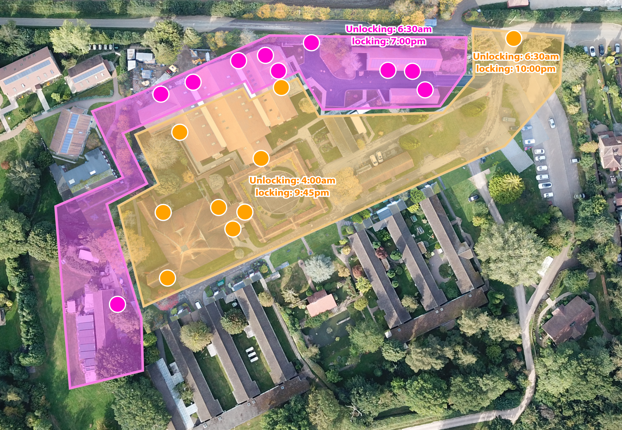
Security Keys Locking Unlocking
V3
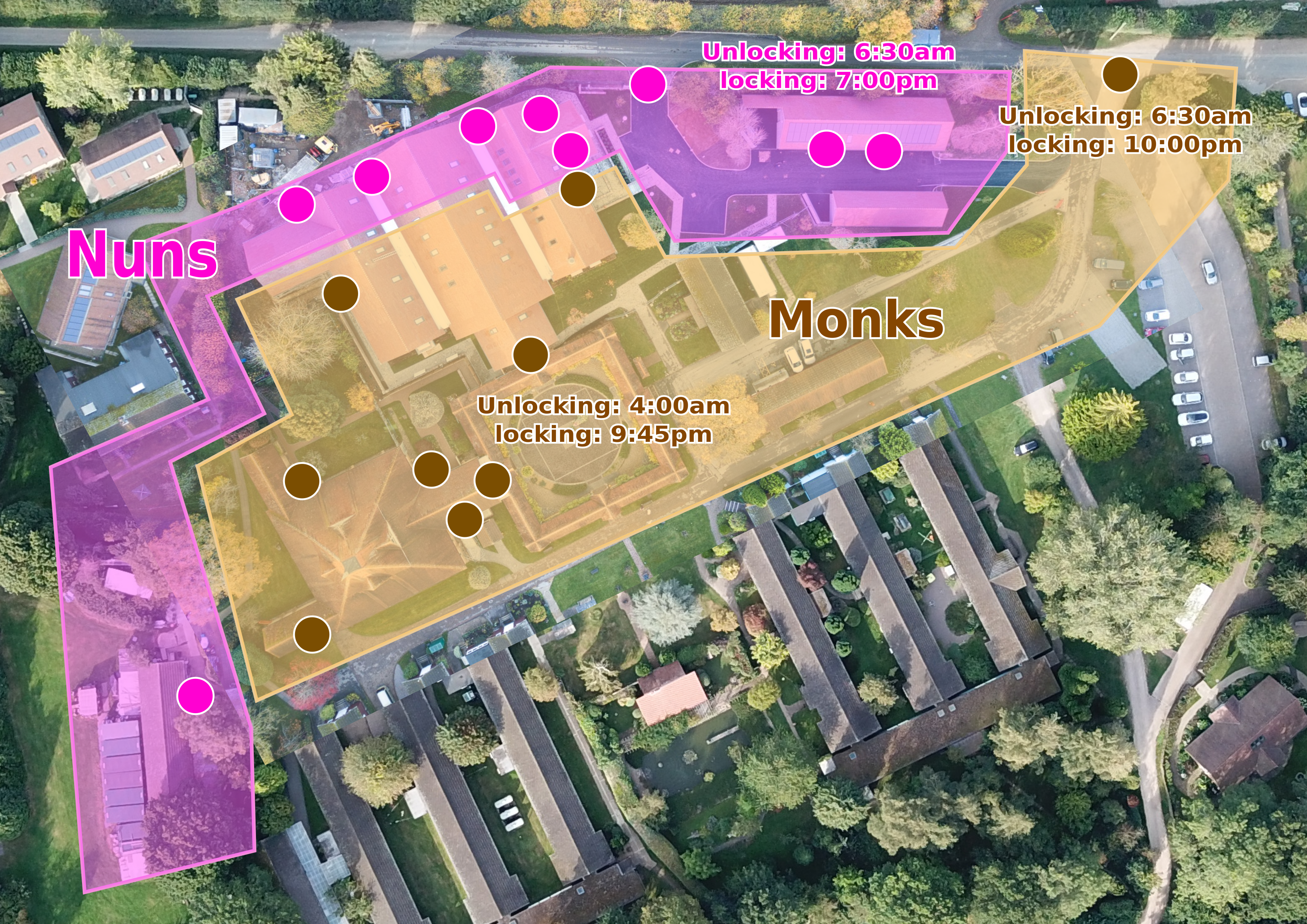

V2